


Terminals
Electrical terminals create controlled conductor endpoints and connection points inside panels, enclosures, switches, breakers, and other equipment. Choose pin terminals when a conductor must be adapted to a compatible equipment terminal, and terminal bars where multiple conductors need organized connection points. Start with conductor size and copper or aluminum compatibility, then confirm terminal geometry, wire range, port or circuit count, equipment interface, voltage rating, and the required crimping or set-screw installation method.
Showing 1–20 of 223 results
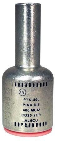
Morris 90976 Straight Solid Pin Terminal, 3/0 AWG Wire / 1/0 AWG Pin
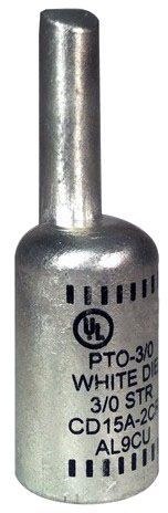
Morris 90990 Offset Solid Pin Terminal, 350 MCM Wire / 250 MCM Pin
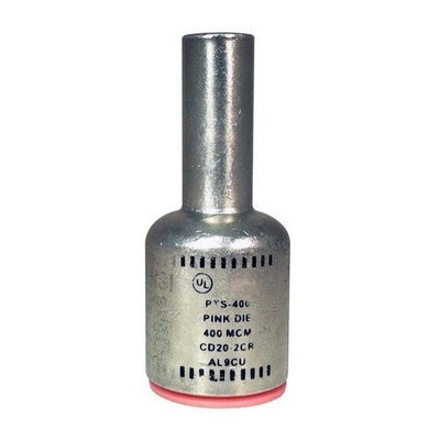
Morris 90971 Straight Solid Pin Terminal, 4 AWG Wire / 4 AWG Pin
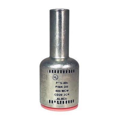
Morris 90974 Straight Solid Pin Terminal, 1/0 AWG Wire / 2 AWG Pin
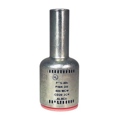
Morris 90975 Straight Solid Pin Terminal, 2/0 AWG Wire / 1 AWG Pin
Morris 90977 Straight Solid Pin Terminal, 4/0 AWG Wire / 2/0 AWG Pin
Morris 90979 Straight Solid Pin Terminal, 300 MCM Wire / 4/0 AWG Pin
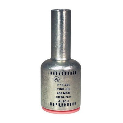
Morris 90970 Straight Solid Pin Terminal, 6 AWG Wire / 4 AWG Pin
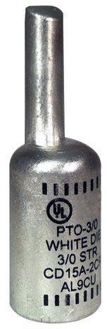
Morris 90986 Offset Solid Pin Terminal, 3/0 AWG Wire / 1/0 AWG Pin

Morris 90980 Straight Solid Pin Terminal, 350 MCM Wire / 250 MCM Pin
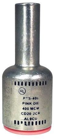
Morris 90982 Straight Solid Pin Terminal, 500 MCM Wire / 350 MCM Pin
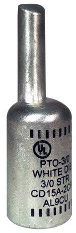
Morris 90993 Offset Solid Pin Terminal, 600 MCM Wire / 400 MCM Pin
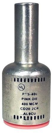
Morris 90983 Straight Solid Pin Terminal, 600 MCM Wire / 400 MCM Pin
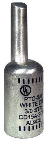
Morris 90987 Offset Solid Pin Terminal, 4/0 AWG Wire / 2/0 AWG Pin
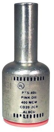
Morris 90984 Straight Solid Pin Terminal, 750 MCM Wire / 500 MCM Pin
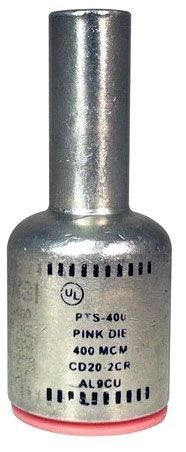
Morris 90978 Straight Solid Pin Terminal, 250 MCM Wire / 3/0 AWG Pin
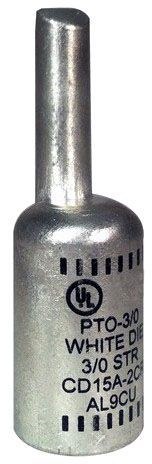
Morris 90988 Offset Solid Pin Terminal, 250 MCM Wire / 3/0 AWG Pin
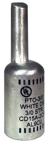
Morris 90989 Offset Solid Pin Terminal, 300 MCM Wire / 4/0 AWG Pin
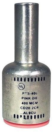
Morris 90981 Straight Solid Pin Terminal, 400 MCM Wire / 300 MCM Pin
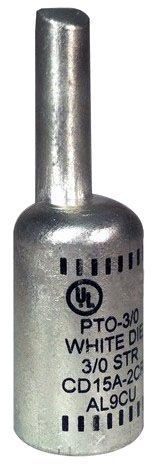
Morris 90991 Offset Solid Pin Terminal, 400 MCM Wire / 300 MCM Pin
About Terminals
How to Choose Electrical Terminals
Electrical terminals should be selected from the conductor and the equipment connection it needs to make. Start with wire size and conductor material, then identify the required terminal geometry, connection method, equipment interface, and number of termination points. Voltage and temperature ratings, available enclosure space, insulation, and installation tooling also matter. A terminal that accepts the conductor physically can still be wrong if its pin size, port configuration, conductor rating, or installation method does not match the equipment.
- Adapting a larger conductor to a smaller compatible equipment connection: use an appropriately sized pin terminal.
- Organizing multiple grounding or neutral conductors at a designated connection point: use the terminal or ground-bar assembly identified for that equipment and application.
- Joining conductors end to end or creating multi-tap splices: use wire connectors and compression splices rather than an equipment terminal.
- Selecting the conductor itself: coordinate termination requirements with electrical wire and cable.
Pin Terminals: Match Both the Wire and the Equipment Side
A pin terminal converts the conductor entering the barrel into a defined solid-pin connection that can fit compatible breakers, switches, panelboards, terminal points, or other equipment. That means the product has two separate dimensions to match: the conductor size entering the terminal and the pin size entering the equipment.
Lumera's current Morris pin-terminal products illustrate this clearly. A terminal can accept a larger conductor while presenting a smaller solid pin to the equipment connection.
Decision rule: record wire size and equipment-terminal capacity separately. Don't assume a terminal selected for the correct conductor automatically has the correct pin dimensions.
Terminals, Lugs and Splices Perform Different Jobs
These products can all terminate conductors, but their final interfaces differ. A pin terminal ends in a solid pin for compatible equipment. A lug typically ends in a tongue with one or more mounting holes for a stud or bolted pad. A splice joins one conductor to another rather than landing the conductor on equipment.
Choosing between them should therefore start with the destination of the conductor. If the wire lands in a compression or set-screw equipment terminal that accepts a pin, a pin terminal may solve an interface problem. If the conductor bolts to a bus or pad, a lug is the more appropriate architecture. If two conductors are being joined inline, use a splice.
Decision rule: identify the final connection point before choosing the termination product.
Conductor Size and Material Must Be Verified Together
Wire gauge alone does not establish terminal compatibility. Copper and aluminum conductors can require different terminal materials, plating, preparation, and product ratings. Some current Lumera terminals are specifically identified for both copper and aluminum conductors, but that capability is product-specific.
A terminal that works with 3/0 copper, for example, should not automatically be assumed suitable for 3/0 aluminum unless the product documentation identifies that conductor material.
Decision rule: check both conductor size and conductor material on the exact terminal. Never infer aluminum compatibility from the terminal's appearance or from its ability to physically accept the wire.
Crimped Pin Terminals Need the Correct Tool and Die
Compression-style pin terminals depend on the crimp to create the conductor connection. The terminal manufacturer can specify a die index, crimp location, and required tooling for the product. Lumera's current Morris straight pin terminal data includes die identification and crimp marks for this reason.
Using a crimper that simply has enough force does not prove that the finished connection is correct. The die geometry has to match the connector system as well.
Decision rule: verify the approved crimp tool and die before ordering project quantities. Follow the marked crimp sequence and inspect the completed termination before placing the insulating cover or landing the pin.
Terminal Bars: Check Wire Range, Circuit Count and Equipment Fit
Terminal bars provide several conductor connection points on one mounted assembly. Current Lumera products include neutral/ground bar configurations with defined conductor ranges, circuit or terminal counts, mounting points, and copper/aluminum compatibility.
More terminal positions do not automatically make a bar suitable for every enclosure. Overall length, mounting-hole positions, conductor entry, wire bending space, and the equipment's approved accessory requirements can all affect fit.
Decision rule: select the bar from conductor requirements and the equipment it will be installed in, not from terminal count alone. For panel-related equipment, coordinate the accessory with the appropriate load center or panelboard rather than treating every terminal bar as universal.
Ground and Neutral Terminations Are Application-Specific
A terminal bar may be manufactured for grounding, neutral, or specified equipment applications, but its role in the electrical system depends on the equipment and installation. Grounded conductors and equipment-grounding conductors should not be moved between connection points simply because the wire sizes fit the same terminal.
Grounding and bonding connections also depend on the conductor, enclosure, equipment, and connection method involved.
Decision rule: use the terminal assembly in the role identified by the equipment and product documentation. For clamps, bonding connectors, grounding lugs, and related hardware, use Lumera's grounding and bonding category.
Port Count Does Not Change the Allowed Conductors per Terminal
A multi-position terminal assembly can accept several conductors across separate positions, but that does not mean multiple wires may be placed under one screw or inside one port. The number and type of conductors permitted at each termination are defined by the connector or equipment manufacturer.
This is particularly important when a project runs short of available terminal positions. Doubling conductors into a terminal that is not identified for that configuration is not a substitute for adding the correct approved connection point.
Decision rule: check both the total number of positions and the permitted conductor quantity per position before sizing a terminal assembly.
Strip Length and Conductor Preparation Affect the Connection
Terminals are designed around a specific conductor insertion depth. Too little stripped conductor can prevent full engagement; too much can leave bare conductor exposed outside the intended connection area. Strands should also remain intact during stripping rather than being cut away to make a conductor fit.
Products intended for aluminum conductors may include oxide inhibitor or specify preparation procedures. Some Lumera pin-terminal and connector products are supplied pre-filled with inhibitor, but that feature should be verified on the exact SKU.
Decision rule: follow the terminal's strip-length and preparation instructions instead of using one standard stripping dimension for unrelated products.
Set-Screw Terminals Depend on Correct Torque
Where a terminal or terminal bar uses set screws, tightening torque is part of the connection specification. Under-tightening can produce an inadequate connection, while excessive torque can damage the conductor, set screw, or connector body.
Large conductor size doesn't provide a reliable visual indication of the required torque. Different connector designs using similar wire ranges can specify different installation values.
Decision rule: use the manufacturer's torque requirement for the exact terminal and conductor configuration rather than a general jobsite rule.
Check Enclosure Space and Wire Bending Before Ordering
A termination has to fit electrically and mechanically. Large conductors can require substantial bending space before entering a pin terminal or terminal bar, while insulating covers and connector bodies add length around the completed connection.
A terminal that looks compact on its own may become difficult to install once the conductor bend, tool access, cover, and adjacent terminals are considered.
Decision rule: review the completed connection inside the available panel or enclosure space, not just the dimensions of the terminal itself.
What to Confirm Before Ordering Electrical Terminals
- Termination function: equipment pin connection, terminal bar, grounding/neutral point, or another identified application.
- Conductor size: match the permitted AWG or kcmil range.
- Conductor material: verify copper, aluminum, or explicitly dual-rated compatibility.
- Equipment interface: confirm pin dimensions, mounting points, or terminal configuration.
- Port or circuit count: provide enough approved connection positions for the project.
- Conductors per terminal: use only the quantity permitted by the product or equipment.
- Connection method: crimped barrel, set screw, or other specified termination.
- Tooling: verify crimp tool, die index, and installation sequence where required.
- Torque: follow manufacturer values for set-screw terminations.
- Ratings: confirm voltage, temperature, insulation, and environmental requirements.
- Space: allow for conductor bending, covers, tool access, and adjacent connections.
Electrical terminals are critical current-carrying connection points. Installation should follow the terminal and equipment manufacturers' instructions for conductor preparation, insertion, crimping, torque, insulation, and mounting. Verify the complete conductor-to-equipment connection rather than selecting a terminal from wire size alone.
Electrical Terminals FAQs
What is an electrical pin terminal used for?
A pin terminal converts the end of a conductor into a defined solid pin that can land in compatible equipment terminals. It is useful when the original stranded conductor is too large or otherwise unsuitable for the equipment's direct connection, provided the terminal is rated for both the conductor and equipment interface.
What is the difference between a terminal and a lug?
A terminal is a broad connection component and can use pin, bar, or other interfaces. A lug typically terminates a conductor with a tongue that bolts to a stud or equipment pad. Select the product from the connection point on the equipment rather than using the terms interchangeably.
Can the same terminal be used for copper and aluminum wire?
Only when the exact terminal is identified for both materials. Some current Lumera terminal products are dual-rated for copper and aluminum, but that is model-specific. Always check conductor-material compatibility along with the allowed wire range.
Can I put two wires under one terminal screw?
Only if the exact terminal or equipment is specifically identified for that number and type of conductors. A terminal that physically has room for two wires is not automatically approved for two-wire termination. Use additional approved terminal positions or connectors when required.
Do crimp terminals require a specific crimping die?
Compression terminals can require a manufacturer-specified crimp tool and die. Die index and crimp markings are part of the connector system. Use the tooling specified for the exact terminal rather than choosing a die only because it appears to fit the barrel.
When should I use a wire splice instead of a terminal?
Use a splice when the purpose is to join conductors to one another rather than land the conductor on equipment. For inline compression splices and insulated multi-conductor connections, compare Lumera's wire connectors instead of adapting an equipment terminal to a splice application.