


Motor Accessories
Motor accessories support the control, protection, connection, and installation of electric motor circuits and equipment. Start with the motor nameplate and system design, then match each accessory to the motor current, control voltage, and compatible starter or control equipment. Enclosure and environmental requirements also need to suit the installation. For larger motor schedules, document each motor and control circuit before standardizing accessories or requesting project quantities.
Showing 1–20 of 58 results
Leviton 1285-GY Switch
Leviton 1282-I Switch
Leviton 1288-I Switch
Leviton 1281-I Switch
Leviton 1256-GY Switch
Intermatic WG1600-11 WG1600-11
Intermatic MOTOR-BOXED,125V 60HZ WG190-15D
Intermatic 125 V Timer Motor WG1571-10
Intermatic Motor-125 V, 60 Hz w/Leads WG1570-10
Leviton 1257-GY Switch
Leviton 1081-GY Switch

Intermatic 125 VAC 60 Hz Timer Motor WG730-14D
Leviton 12021-2I Switch
Intermatic 208/277 V 60 HZ Timer Motor WG1603-11D

Intermatic 125 VAC 60 Hz Timer Motor WG1570-10D
Intermatic Timer Motor WG436-20
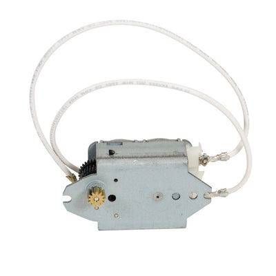
Intermatic 125V 60HZ Timer Motor WG433-20D
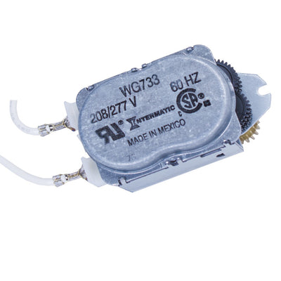
Intermatic 208-277 VAC 60 HZ Timer Motor WG733-14D
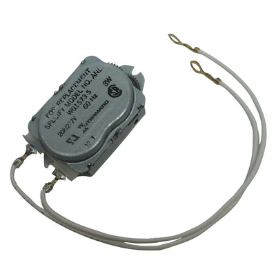
Intermatic 208-277 VAC 60 HZ Timer Motor WG1573-10D
Intermatic Timer Motor WG736-14
About Motor Accessories
How to Choose Motor Accessories for the Motor and Control Circuit
Motor accessories should be selected from the electrical and control requirements of the motor system rather than by appearance or enclosure size. Start with the motor nameplate, supply voltage, phase, full-load amperage, and the control scheme used to start and stop the equipment. Then verify the accessory’s electrical rating, control voltage, compatibility, mounting method, and environmental requirements. A component that fits physically is not automatically compatible with the starter, motor, or control circuit.
- Planning upstream overcurrent protection? Compare circuit breakers by panel and circuit requirements.
- Housing motor-control components? Review NEMA electrical enclosures.
- Bringing flexible cable into the enclosure? Match it with suitable cable glands and cord grips.
Start With the Motor Nameplate, Not the Accessory Catalog
The motor nameplate provides the basic electrical information needed before control or protection components can be selected. Supply voltage, phase, frequency, full-load amperage, horsepower, and other motor-specific data can affect the surrounding equipment. Two motors with the same horsepower are not necessarily interchangeable from a control standpoint if their voltage or current requirements differ.
For example, a 5 hp motor on one system can require different control hardware from a 5 hp motor operating at another voltage. Decision rule: record the exact motor nameplate data before selecting any accessory associated with switching, overload protection, or control.
Motor Current and Accessory Ratings Have to Match the Application
Motor circuits behave differently from simple resistive loads because starting current and operating conditions matter. A control component should therefore be evaluated using the manufacturer’s motor or horsepower ratings where applicable, not only a general amp number printed on the device. The exact motor and duty determine whether the component is suitable.
A device carrying 10A continuously does not automatically qualify to start a motor that also draws 10A at normal running load. If the accessory switches or protects motor current, use the product’s stated motor ratings and application information. Upstream short-circuit and branch-circuit protection should be coordinated separately with the correct breaker specification.
Control Voltage Must Match the Starter or Control Circuit
Motor systems often separate the power circuit from the control circuit. The power side carries the motor current, while the control side operates coils, relays, pushbuttons, sensors, or other devices. These two circuits can operate at different voltages, so an accessory that belongs in the control circuit must match that control voltage specifically.
A motor supplied from a 480V three-phase circuit may still use a lower-voltage control circuit. That means the accessory cannot be chosen from motor supply voltage alone. Decision rule: verify whether the component connects to the power circuit or the control circuit, then match its voltage rating to that exact side of the system.
Contactor and Overload Functions Should Not Be Confused
In a conventional magnetic motor starter, the contactor performs the switching while the overload relay monitors motor current and interrupts the control circuit when an overload condition persists. They perform different jobs and are selected using different criteria. Replacing one does not replace the function of the other.
For a three-phase motor starter, the contactor has to switch all required power conductors while the overload device must be selected and adjusted around the motor’s actual current requirements. Lumera’s motor-starter guidance also emphasizes that overload settings are based on motor nameplate information rather than simply copying the upstream circuit-breaker rating.
Confirm Mechanical and Electrical Compatibility With the Existing Equipment
Motor accessories can be highly system-specific. Mounting dimensions, terminal arrangement, coil voltage, auxiliary-contact arrangement, trip range, manufacturer series, and the starter or enclosure they are designed to fit can all affect compatibility. Similar-looking components should not be treated as universal replacements.
If an existing starter needs a replacement accessory, record the manufacturer, series, catalog number, and electrical ratings before ordering. For conductor connections associated with the control or power circuit, use appropriately selected wire connectors and compression splices rather than adapting a connection that does not match the conductor.
Choose the Enclosure Around the Environment and Equipment Inside
Motor-control accessories installed in an enclosure need enough space for the equipment, wiring, conductor bending, and service access. The environment also determines the enclosure protection required. A dry indoor equipment room and an outdoor pump installation should not automatically use the same housing.
A starter assembly with a contactor, overload device, control transformer, and terminal connections can require substantially more internal space than one small control component. Select the enclosure after the internal arrangement is known. Lumera’s NEMA enclosure selection provides options for equipment housing, while cable entries should remain compatible with the enclosure rating.
Plan Cable Entry, Strain Relief, and Terminations Together
Motor leads and control cables should enter the enclosure without transferring pulling or twisting force directly to internal terminals. Flexible cable may require a cord grip or cable gland selected around the cable outside diameter, enclosure opening, and installation conditions.
For example, a motor cable entering the bottom of an outdoor enclosure should be treated as an entry-system problem as well as a wiring problem. Use suitable cord grips and cable glands where strain relief or sealing is required, then match internal terminations to the conductor size and material.
Coordinate Timers and Automatic Controls With Motor Load Ratings
Motors used for pumps, ventilation, or other scheduled equipment may be operated by a timer or another control signal. The controlling device must either be rated to switch the motor load directly or operate an appropriately selected contactor that carries the motor current.
A small wall timer should not be assumed capable of switching a larger motor because its general amp rating appears sufficient. When scheduling is part of the system, compare Lumera’s time switches and timers by motor-load rating and control method, and use an intermediate contactor where the control is intended only to operate the coil.
Grounding and Bonding Remain Part of the Motor Installation
Metal enclosures, raceways, and motor equipment can have grounding and bonding requirements independent of the control components installed inside. A mechanical mounting connection should not be assumed to provide every required bonding path unless the equipment and installation method specifically establish that function.
Where purpose-built grounding hardware is required, coordinate the installation with Lumera’s grounding and bonding components. Permanent motor and motor-control wiring should be installed and verified by a qualified electrician in accordance with the motor, accessory, and control-equipment instructions and the requirements applicable to the project.
Ordering Motor Accessories for a Larger Project
For projects with multiple motors, organize the material schedule by motor identification, horsepower, voltage, phase, nameplate full-load amperage, control voltage, starter or control-equipment series, accessory function, enclosure location, and quantity. Repeat electrical buyers can also review Lumera Electric’s trade account options for ongoing project purchasing.
Request a Motor Accessories Project Quote
For larger quantities or projects with several motor-control configurations, request a project quote after the motor and control schedule has been verified.
Have these details ready:
- Motor horsepower
- Motor supply voltage and phase
- Nameplate full-load amperage
- Existing starter or control-equipment manufacturer and series
- Control voltage
- Accessory function required
- Indoor or outdoor installation environment
- Enclosure requirements
- Conductor and cable-entry requirements
- Quantity
For projects with several motors, you can also submit your motor-control schedule so each accessory remains tied to the correct motor, control voltage, and equipment configuration.
Motor Accessories FAQs
What is the difference between a contactor and an overload relay?
A contactor switches power to the motor, while an overload relay monitors motor current and causes the contactor to drop out when an overload condition persists. They solve different problems and normally work together in a magnetic starter. Lumera’s magnetic motor starter guide explains the power and control circuits in more detail.
How do I choose an accessory for an existing motor starter?
Start with the starter manufacturer, series, catalog number, control voltage, motor horsepower, voltage, phase, and nameplate current. Then confirm that the replacement component is identified as compatible with that exact equipment. Mechanical fit alone is not enough, especially for overload elements, coils, auxiliary contacts, or other starter-specific components.
How is an overload relay sized for a motor?
Overload protection is selected using motor-specific information, especially the full-load amperage shown on the motor nameplate and the instructions for the overload device. It should not simply be copied from the branch-circuit breaker rating. Breakers and overload relays perform different protection functions within the motor circuit.
Do I need a separate enclosure for motor-control accessories?
That depends on whether the accessory is already part of enclosed equipment and on the installation environment. Open motor-control components normally require an appropriate enclosure as part of the complete assembly. Where a separate housing is needed, compare electrical enclosures by internal space and environmental requirements.
Can a timer control a motor directly?
Only when the timer is specifically rated for that motor load and application. For larger motors, a timer often operates a contactor rather than carrying the motor current itself. Lumera’s timer selection includes equipment-oriented time switches, but the exact motor and control ratings still have to be checked before installation.