


Wire Connectors
Wire connectors and compression splices join conductors in feeder, service, control, and equipment wiring where the connector must match the exact conductor combination. Lumera’s current assortment includes copper and aluminum compression splices, long- and short-barrel styles, reducing splices, and insulated service-entrance configurations. Choose by conductor size and metal, splice configuration, and required crimp system. For project work, confirm the connector, die requirements, and enclosure plan before standardizing quantities.
Showing 81–100 of 428 results
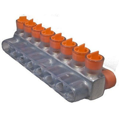
Morris 97422 Clear Insulated Connector, Dual Side Entry, 350 MCM, 8-Port
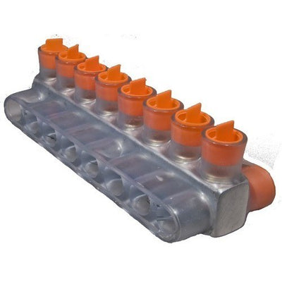
Morris 97402 Clear Insulated Connector, Dual Side Entry, 250 MCM, 8-Port
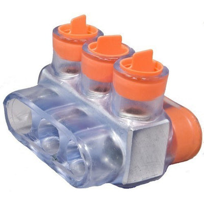
Morris 97434 Clear Insulated Connector, Dual Side Entry, 500 MCM, 3-Port

Morris 97432 Clear Insulated 2-Conductor Connector, Dual Side Entry, 500 MCM
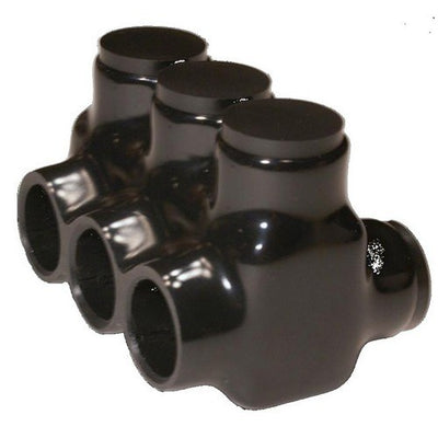
Morris 97693 Black Insulated Connector, Dual Side Entry, 500 MCM, 3-Port
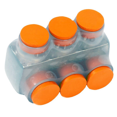
Morris 97473 Clear Insulated Connector, Single Side Entry, 2/0 AWG, 3-Port
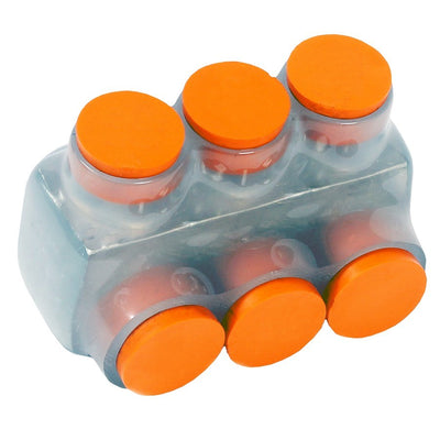
Morris 97450 Clear Insulated Connector, Single Side Entry, 4 AWG, 3-Port
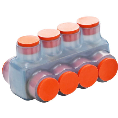
Morris 97426 Clear Insulated Connector, Dual Side Entry, 750 MCM, 4-Port
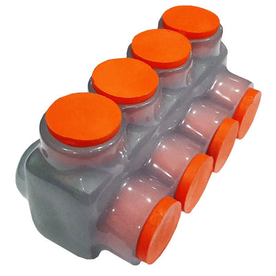
Morris 97474 Clear Insulated Connector, Single Side Entry, 2/0 AWG, 4-Port

Morris 97451 Clear Insulated Connector, Single Side Entry, 4 AWG, 4-Port
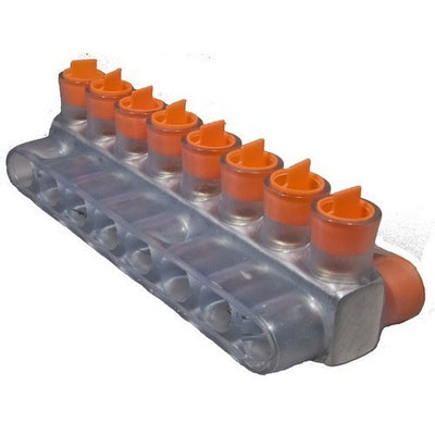
Morris 97428 Clear Insulated Connector, Dual Side Entry, 750 MCM, 8-Port
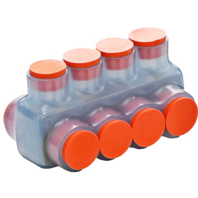
Morris 97436 Clear Insulated Connector, Dual Side Entry, 500 MCM, 4-Port
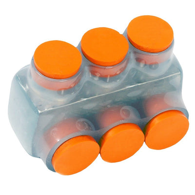
Morris 97465 Clear Insulated Connector, Single Side Entry, 1/0 AWG, 3-Port

Morris 97459 Clear Insulated Connector, Single Side Entry, 2 AWG, 4-Port
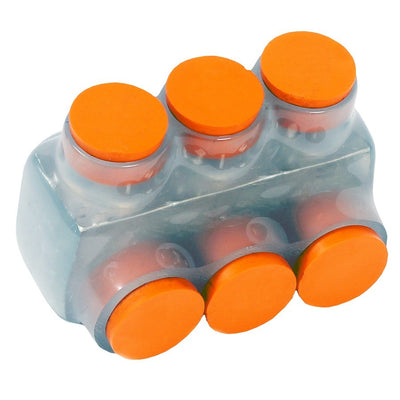
Morris 97458 Clear Insulated Connector, Single Side Entry, 2 AWG, 3-Port
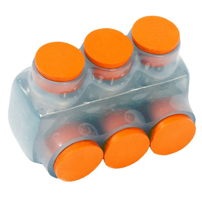
Morris 97488 Clear Insulated Connector, Single Side Entry, 250 MCM, 3-Port
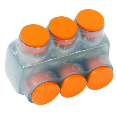
Morris 97481 Clear Insulated Connector, Single Side Entry, 3/0 AWG, 3-Port
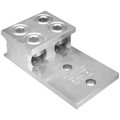
Morris 90952 Aluminum Mechanical Lug, Two-Conductor 2-Hole, 1000 MCM - 350 MCM

Morris 97513 Black Insulated Connector, Single Side Entry, 4 AWG, 3-Port

Morris 97503 Clear Insulated Connector, Single Side Entry, 500 MCM, 4-Port
About Wire Connectors
How to Choose Wire Connectors & Compression Splices
Wire connectors should be selected from the conductors being joined, not from barrel color or outside diameter. For compression splices, start with conductor size and metal, then determine whether both sides are the same size, whether the project calls for a long- or short-barrel connector, and which crimp tooling the manufacturer specifies. The finished splice also needs a suitable accessible enclosure and insulation system. Large-conductor connections are engineered assemblies, so every part of the splice should be confirmed before installation.
- A conductor ending on equipment rather than another conductor points to electrical lugs.
- A large splice that needs accessible working space belongs in a junction box or enclosure.
- A grounding-electrode connection calls for ground clamps, not a general splice.
- Raceway entries around the splice point use suitable electrical fittings.
- A cable entering an enclosure without being spliced may need a cable gland or cord grip.
Match the Compression Splice to Conductor Size and Metal
Conductor size and material narrow the connector choice before anything else. A splice for copper conductors should not be assumed suitable for aluminum, and a connector marked for one conductor range should not be forced onto another. The same rule applies when both sides of the splice use different gauges. For example, two 4/0 AWG copper conductors need a connector listed for that exact combination and conductor material.
Decision rule: read the conductor markings first, then match the connector’s permitted size and metal. If the wire itself has not been finalized, review the project’s electrical wire and cable specification before ordering connectors.
Long-Barrel vs. Short-Barrel Compression Splices
Barrel length changes the physical space available for crimps and the overall length of the finished connection. Long-barrel connectors generally accommodate more crimp locations, while short-barrel versions can help where enclosure space is limited. That does not make one universally better; the project specification and manufacturer’s installation instructions control the choice.
A 250 kcmil splice inside a crowded enclosure may create a real space constraint that would not exist in a large pull box. If enclosure space is tight, evaluate connector length alongside the required crimp pattern before selecting the barrel style. The enclosure still needs adequate accessible space for the complete finished splice.
Use Reducing or Insulated Service Splices Only for Their Intended Connection
A reducing splice has different conductor openings at each end, allowing unlike conductor sizes to be joined without improvising adapters. Lumera’s current assortment includes configurations such as 4/0 AWG to 1/0 AWG service connections. Insulated service-entrance splices address a different need by incorporating insulation around the connector body rather than leaving a bare compression barrel.
Decision rule: if the two conductors differ in size, choose a connector specifically designed for that pair; if the project requires an insulated service configuration, verify the exact product and installation method rather than adding field insulation by assumption. For equipment terminations, switch categories entirely and use a listed lug.
Confirm the Crimping Tool, Die, and Crimp Pattern Before Ordering
A compression connector only performs as intended when it is installed with the tooling specified for that part. The manufacturer determines the die system and number or location of crimps. A visually tight joint is not proof that the compression was made correctly. On a 350 kcmil splice, discovering after delivery that the crew lacks the required die can stop the installation even though the connector itself is correct.
Decision rule: verify connector part number, tool compatibility, die identification, and required crimp sequence as one package. Lumera’s wire connector and splicing guide covers the selection factors that should be checked before the splice is made.
Plan the Enclosure, Insulation, and Related Hardware Around the Splice
The connector is only one part of the finished installation. A 600 kcmil splice may need substantial enclosure space for conductor bending and positioning, while raceway entries require their own fittings and the completed connection must retain the insulation and environmental protection required by the wiring system. Splices also need to remain accessible where the installation rules require access.
If the job is actually a grounding or bonding connection, move to Lumera’s broader grounding and bonding hardware instead of adapting a general compression splice. Large-conductor compression work should be performed by qualified electrical personnel using the connector manufacturer’s preparation, crimping, and insulation instructions.
Ordering Wire Connectors for a Project
For feeder, service, distribution, or equipment projects, organize the connector schedule by conductor size on each side, copper or aluminum construction, same-size or reducing configuration, barrel style, insulation requirement, crimp tooling, enclosure location, and quantity. Keeping those details together prevents connectors that look similar from being mixed across circuits. Project buyers can also review Lumera Electric’s trade account options.
Request a Wire Connector & Compression Splice Quote
For larger quantities or projects with several conductor sizes, request a project quote after the conductor and connector schedule has been established.
Have these details ready:
- Conductor size on each side of the splice
- Copper, aluminum, or approved mixed-metal requirement
- Same-size or reducing connection
- Long- or short-barrel requirement
- Insulated or bare connector requirement
- Specified crimp tool and die system
- Splice enclosure and available space
- Indoor, outdoor, service, or other installation condition
- Quantity by conductor combination
For multi-circuit projects, you can also submit your connector schedule so conductor sizes, splice types, tooling requirements, and quantities remain coordinated.
Wire Connector & Compression Splice FAQs
What is the difference between a compression splice and a lug?
A compression splice joins one conductor to another, while a lug terminates a conductor on equipment, a bus, or another connection point designed for that lug. They are not interchangeable. If the conductor ends at equipment instead of continuing into another wire, start with Lumera’s electrical lugs rather than a splice barrel.
Can I use a copper compression splice on aluminum wire?
No, unless the exact connector is specifically listed for the conductor materials being joined. Copper-only connectors should not be substituted on aluminum conductors simply because the wire fits. Material compatibility is a core selection requirement. Lumera’s wire connector comparison guide reinforces the same principle: follow the connector’s listing and installation instructions.
What is the difference between long-barrel and short-barrel splices?
Long-barrel splices provide more barrel length for the manufacturer’s required crimp pattern, while short-barrel versions reduce the physical length of the finished connection. The correct option depends on the specification, conductor, tooling, and available enclosure space. Don't substitute one for the other without checking the installation instructions for the exact connector.
What is a reducing compression splice?
A reducing splice joins conductors of different sizes by providing a different bore at each end. For example, the current Lumera assortment includes service-entrance configurations that connect 4/0 AWG conductors to smaller conductors. The connector still has to be listed for the exact two sizes and conductor materials used on the project.
Do compression wire connectors need a special crimping tool?
Yes. Large compression splices require the crimping tool and die system specified by the connector manufacturer. The correct connector alone is not enough; die identification and the required crimp sequence are part of the installation. Plan that tooling before material arrives, especially when the splice will be installed inside a large junction or pull enclosure.